Spring Pack
Background
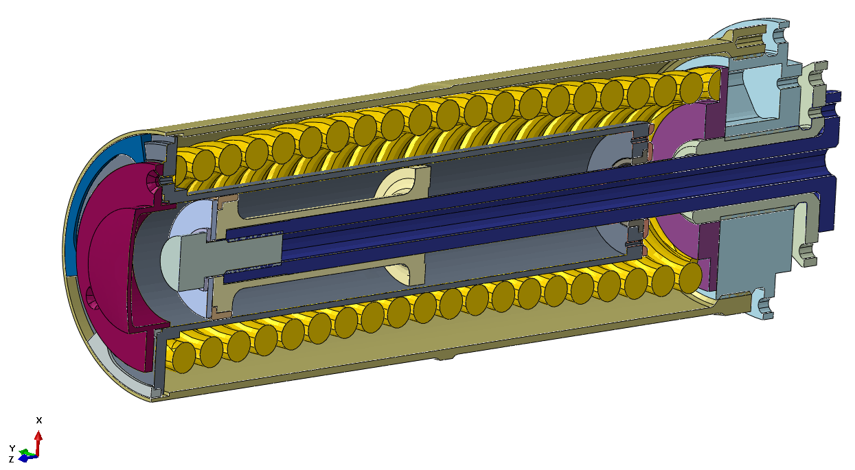
A Spring Pack (SP), used to allow the separation between two stages of a space rocket in which is installed, required some delicate simulations of what is happening during the launch phase. The SP is a quite complex system (Figure 1), but basically it consists of a preloaded coil spring.

Figure 1 – Spring Pack Assembly before compression (“Open” condition)
The Challenge
The load conditions that arise during the launch phase would require a random vibration analysis, and this in turn means that the models have to be linear. Our Customer tried very hard to linearize the complex SP assembly, but everything they came up with was not anymore representing in an adequate way its behaviour (a pre-compressed spring, in contact at the two ends and that very likely would hit the internal cylinder and the outer housing, could really not be simplified into a linear model).
A non linear dynamic analysis was identified as being the only way to succeed and CG CAE was chosen as the partner to perform those simulations, because of our experience in dealing with highly non linear models, and in this particular case there are many contact pairs.
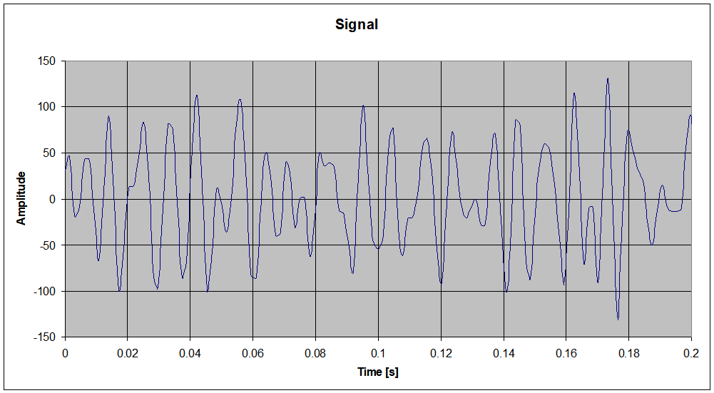
Nonetheless a non linear model cannot be approached with the numerical techniques used to solve random vibrations problems; because our Customer was interested only in the first milliseconds of the launch phase and because they would have anyway tested the part on the test bench, it was decided to apply as a load case the signal that they would have used to drive the test equipment (Figure 2). In conclusion, a non linear dynamic analysis was carried out imposing an acceleration, rapidly varying in time, thus coming to a time history analysis.

Figure 2
The FE Model
Due to the rapidly varying acceleration, a very small integration time step was expected and for this reason some time was spent, using our wide experience, to find the best compromise between mesh size and solution time.
As already said, the model foresees numerous contacts among all the parts and care was taken in representing them in the best way possible.
A total of three steps have been applied: the first two are static analyses and have the aim to pre-compress the spring, and the third is the actual dynamic simulation.
Some results
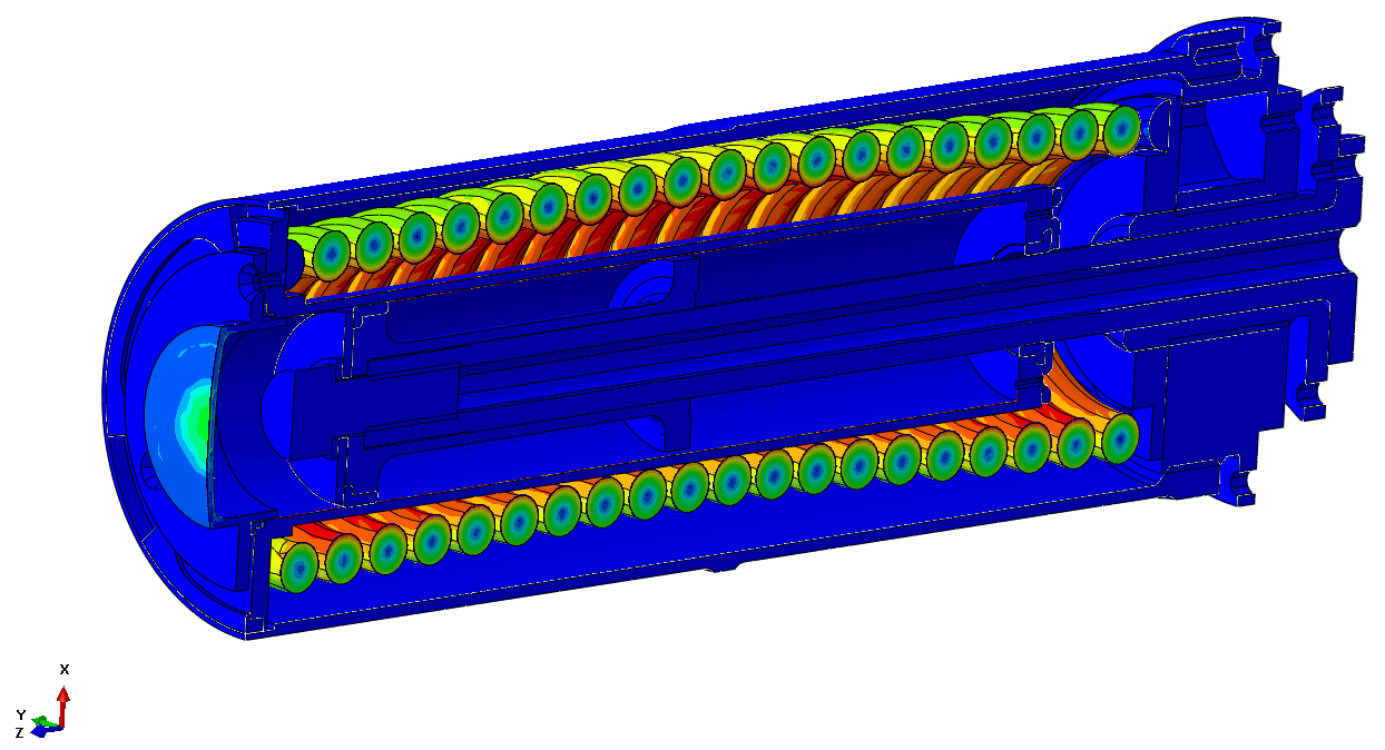
Figure 3 shows the condition where the spring is compressed into its final position; due to the flattening of the incomplete coils, as it can be seen the compression is already generating a bent and some coils are already touching the internal rod.


Conclusions
The results of the dynamic simulation (see animation in Figure 4) showed that the spring was hitting hard both the outer case and the internal cylinder, generating stress levels above the allowable limit for the material (in particular some areas would have been plasticized). Nevertheless our Customer decided to anyway test the part, and after the test they have found some areas that were actually indented by the movement of the spring; they therefore redesigned the parts by allowing more room to the spring, thus reducing the contact pressure generated by the hits. The model was updated and re-run: the comparison with the previous solution was giving enough confidence that the SP would have survived the test without additional design loops, and this is what actually happened.
Figure 4
