An aluminium tube with a rectangular cross section (see Figure 1) is used as a crash absorbing structure. In those kind of structure, there are many details to take care about in order to get a structure that behaves correctly: average and peak decelerations, residual length of the crasher being just a couple of them.

Figure 1 – Crash structure
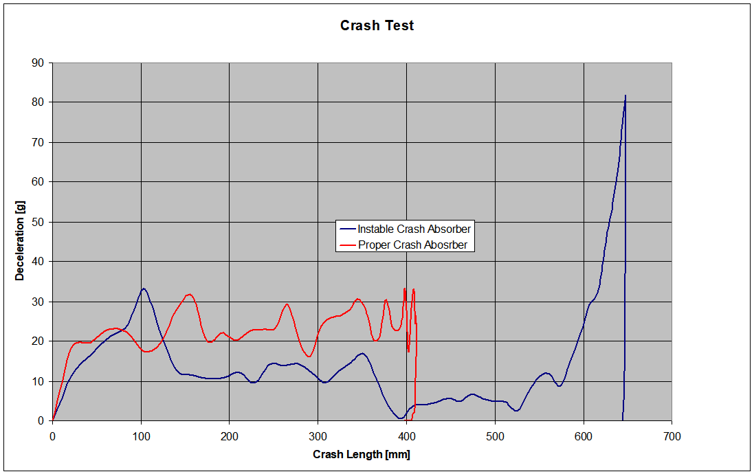
Our Customer designed the aluminium tube following their experience but when they went to the actual test, they failed to pass it due to a too high deceleration peak (around 80 g), given by the hit of the trolley against the rigid wall. Basically the crasher did not work as expected and when the trolley hit the wall there was still too much kinetic energy, thus the huge deceleration peak.
They decided to run some simulations to better understand what happened and CG CAE was chosen as the partner to perform those analyses, because of our experience in dealing with highly non linear and dynamic phenomena.
The first thing we did was to simulate the structure as it was designed, trying to find the material properties to model the damage initiation and evolution: this could guarantee that the high speed phenomenon would have been correctly represented.
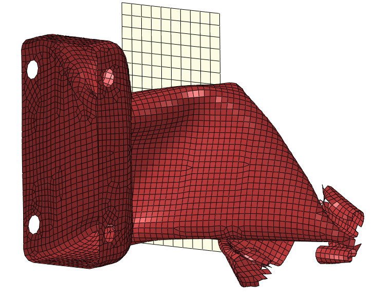
Figure 2 shows the Finite Element Model with the wall; the tube was modelled with shell elements and the wall has been considered as rigid.
Due to the high speed phenomenon, an Explicit approach has been chosen to solve the model.

Figure 2 – The FE model of the tube
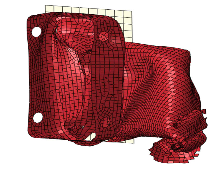
Figure 3 shows the status at t = 40 ms and at t = 80 ms (end of simulation): it is clear that something has gone wrong.

Figure 3: t = 40 ms

Figure 3: t = 80 ms
In particular it is clear that the tube has buckled and therefore it could not work in the proper way to actually absorb energy.
Some linear buckling analyses showed that this was exactly the problem.
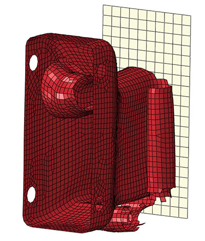
Therefore linear buckling analyses were used to modify the structure geometry in order to raise the buckling load and then the crash simulation was run again, coming to the results shown in Figure 4.

Figure 4 – End of the crash
for the modified structure
Figure 5 contains the comparison between the initial geometry and the modified one in terms of the deceleration vs. crash length.

Figure 5 – Deceleration vs. crash length for the two configurations
Figure 6
Privacy Settings
This website uses cookies to improve your experience while you navigate through the website.
View the Cookie Policy View the Personal Data Policy
Google Analytics is a web analytics service provided by Google Ireland Limited ("Google"). Google uses the collected personal data to track and examine the usage of this website, compile reports on its activities, and share them with other Google services. Google may use your personal data to contextualize and personalize the ads of its advertising network. This integration of Google Analytics anonymizes your IP address. The data sent is collected for the purposes of personalizing the experience and statistical tracking. You can find more information on the "More information on Google's handling of personal information" page.
Place of processing: Ireland - Privacy Policy
Additional consents: