The Dimensional Factor in Fatigue Analyses
Historically, fatigue tests are performed by rotating bending, i.e. cylindrical specimens are rotated while a load stresses them with a fixed direction in time: this way an alternating cycle from zero is easily obtained.
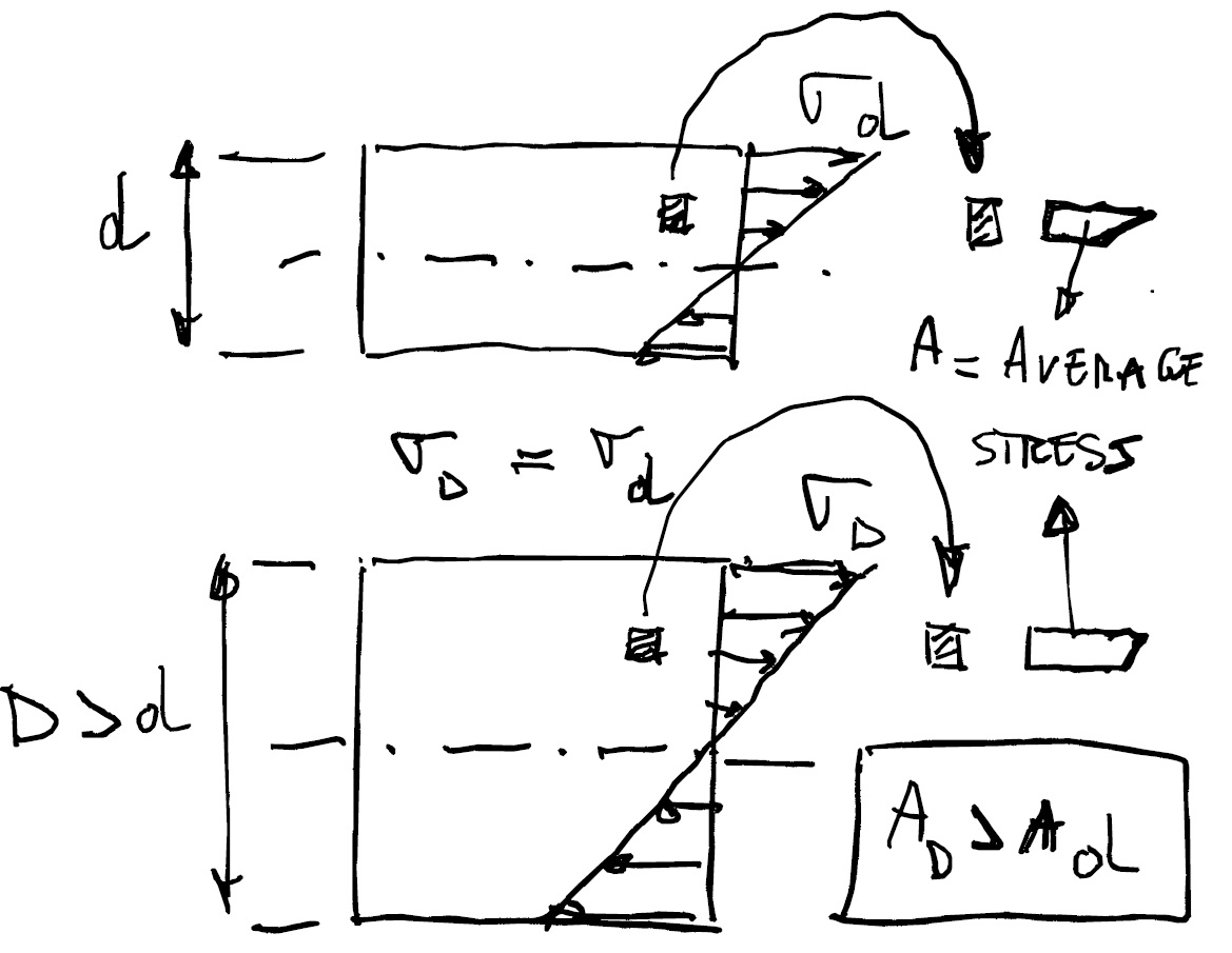
Generally the specimens have a rather small diameter (maximum 10 mm) and it was discovered that, for specimens of larger size, the fatigue limit decreased under the same conditions, i.e. same material and same maximum stress. This evidence can be explained by the fact that, for a specimen with size D > d, the stress gradient is smaller at the same maximum stress, and consequently the average stress on the single grain of material is higher and therefore more subjected to crack initiation (see figure 1).
On the basis of this experimental evidence, nowadays more and more frequently axial tests are used instead of rotating bending, for which there is no stress gradient; the machines required are somewhat more complex and these tests, therefore, are more expensive.
Several comparisons between the rotating bending test and the axial test on the same material have shown a relationship between the two fatigue limits obtained:
sFaa = 0.7 x sFab
sFaa being the axial alternating fatigue limit and sFab the bending alternating fatigue limit. From here it can be seen that the axial tests give more conservative values.
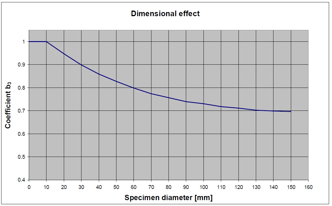
On the other side, when performing fatigue calculations using the values obtained from the alternating fatigue bending tests (sFab), a knock down factor has to be used in order to avoid the risk of being too “optimistic”, and this is the dimensional factor, whom graph is represented in figure 2.
It can be seen that above 150 mm diameter the dimensional factor would knock down the fatigue limit at 70% of the value obtained from standard coupons, thus practically resulting like if sFaa was used.
Nonetheless there is all the “region” below the 150 mm diameter where using sFaa would be conservative, maybe too conservative.
Chapter 10 of the book Computational Structural Engineering illustrates how the dimensional factor is used in fatigue calculations when stress values are coming from a Finite Element Model.
