The design of the Primary Roll Over Structure was required for a high perfomance electric single seater.
Because those structures are, by definition, placed on the highest position of sport vehicles, they have to be as light as possible, in order to try and keep the center of gravity of the car as low as possible.
Moreover the Customer strongly wanted to comply with the requirements of the FIA regulations for Formula One cars, despite the vehcile was not meant to run together with other competitors.
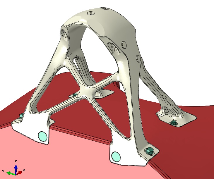
Final Design
The Challenge
As mentioned, the part needed to be light, strong to resist the severe tests from the FIA regulations and as cheap as possible.
To meet those targets, the DMLS (the so called 3D printing) production process was found to be the best one, because it offers the possibility to use light weigth materials, such Aluminium and Titanium, and it allows for “strange shapes”, thus giving the maximum freedom to the Topological Optimization.
CG CAE was chosen as a partner to support the design team with all the simulations required, starting exactly from the topological optimization, because of our wide experience in Motorsport, in advanced non linear calculation techniques, such as elastic-plastic material behaviour and the simulation of bonded joints.
The FE Models
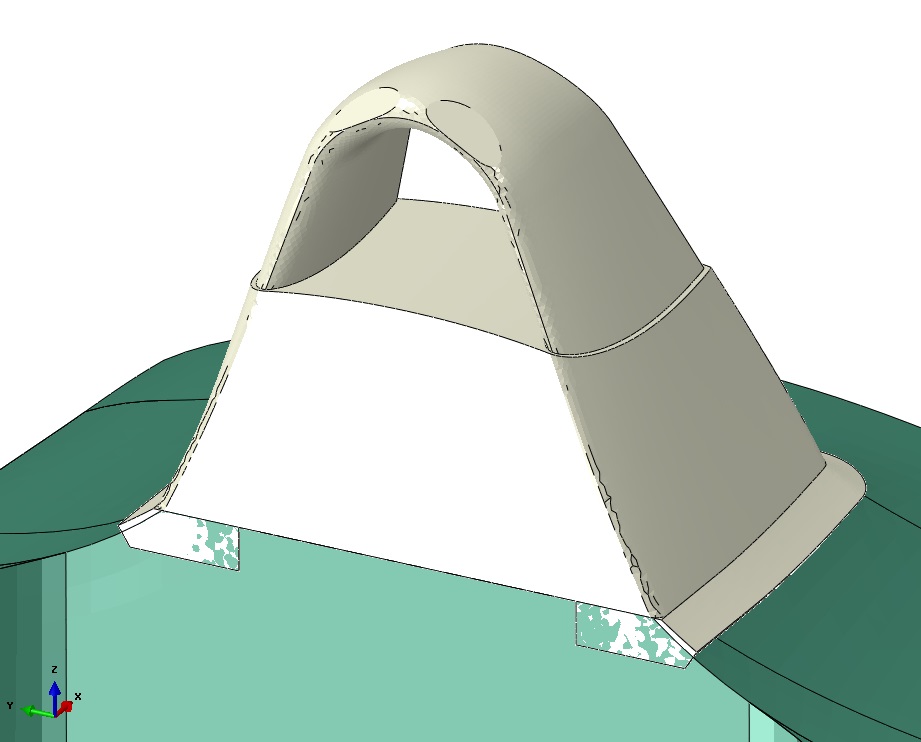
Starting point for Topological Optimizations is the Design Space, i.e. the volume that the structure can fill, respecting the surrounding components or some other geometric constraints: in this case the inlet area was defined by aerodynamic matters.
To better represent the real stiffness of the assembly, a portion of the monocoque (green part) was considered into the model, but it was not included into the structure being optimized (white part).
Design Space
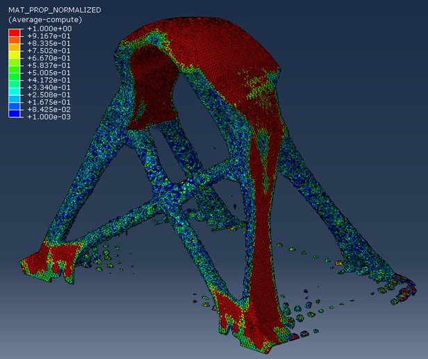
The "dirty" result from the topological optimization
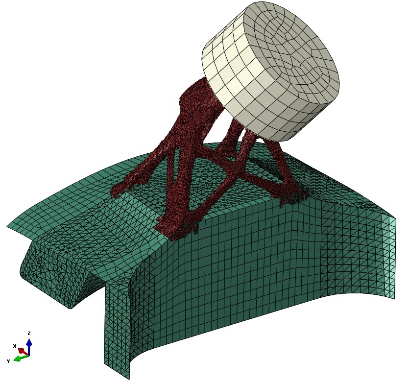
Cleaned model
The topological calculations were run linearly to save time, with the intent to validate them with non linear simulations once the first “reasonable” results were obtained.
Here above (left) the final “dirty” geometry obtained from the optimizations loops is shown, which was worth to deeper analyze. Therefore the model was extracted, “cleaned” (removal of non connected portions) and run with non linear material proporties and the pad used to apply the force from the FIA regulations (figure on the right).
Some results
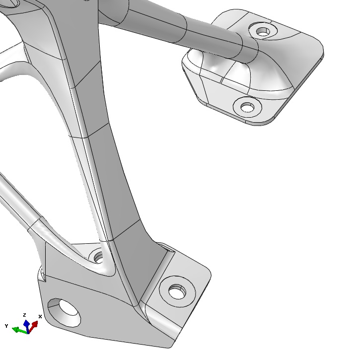
Once the extracted model has been validated, the structure needed to be “engineered”, i.e. it has been made feasible through iterations between the Design and the Production departments. As an example, the feet of the Roll Hoop needed to be fixed to the monocoque, and a fixation system was required: due to the extremely high forces passing through these feet, the decision of using bonding and bolts was taken; and this was against the common practice stating that if two or more connection means are to be used, then each of them should resist on its own to the forces passing through the joint: advanced simulation of glue damage initiation and propagation and non linear material properties for the bolts allowed to overcome that principle.
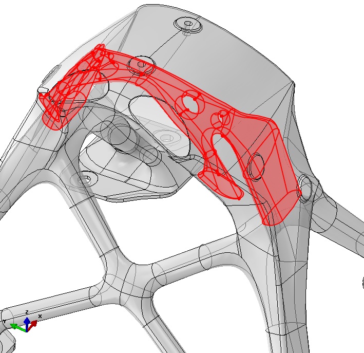
The two pictures here below show the detail of the front and rear flanges (left) and the detail on the hollow section obtained by the topological optimization.
Flanges are bonded and bolted to the monocque
The red surfaces bound the "internal hollow volume"
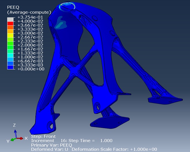
Equivalent Plastic Strain
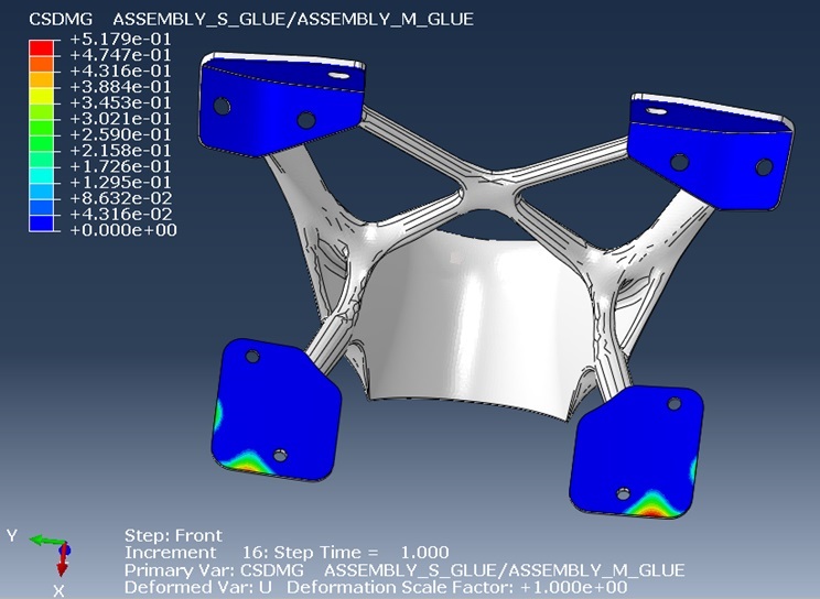
Damage in the glue
The last step has been to rebuild the FE Model of the engineered structure and rerun the load cases foreseen by the FIA regulations.
A certain amount of residual deformation is allowed and therefore the plastic capability of the alumnium being used has been exploited up to the maximum limit of 4% (see picture above on the left).
The figure on the right shows the damage distribution in the glue layer, indicating that some areas are heavily damaged, but they do not totally fail: the presence of the bolts helped to achieve this result.
Conclusions
This is a good example of an advanced design process:
Toplogical Optimization has to be undertaken since the initial phases
The strength of the gemoetry obtained by the optimization process has to be validated, by extracting the “rough” model and simulating the actual load cases, with all the expected non linearities (geometric, contact and material)
Design office has to engineer the geometry and make it produceable considering the manufacturing process choosen
Final design needs to be validated again with final simulations.
CG CAE was the right partner to support the design process with all the advanced simulations that were required to achieve the ambitious targets set by the Customer.
Google Analytics is a web analytics service provided by Google Ireland Limited ("Google"). Google uses the collected personal data to track and examine the usage of this website, compile reports on its activities, and share them with other Google services. Google may use your personal data to contextualize and personalize the ads of its advertising network. This integration of Google Analytics anonymizes your IP address. The data sent is collected for the purposes of personalizing the experience and statistical tracking. You can find more information on the "More information on Google's handling of personal information" page.